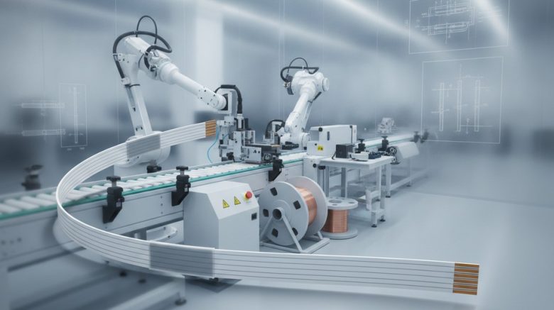
A production line for intermittently bonded ribbon is used to manufacture flexible fiber groups for contemporary, high-count cable architectures. It ensures fibers are aligned for expedited mass fusion splicing, yet accommodates the group’s flexibility within a compact cable core.
Unlike fully bonded ribbons, intermittent bonded ribbons feature localized bonds at predetermined intervals. This strategic placement keeps the fibers in an organized sequence while the ribbon can bend and roll into circular loose tubes and other confined spaces.
Fiber network engineers apply this technique when faced with constraints in duct space, splice closures, and equipment racks. A properly engineered ribbon cable facilitates dense network deployments in data centers, telecom backbones, metro networks, FTTx feeder systems, and 5G transport networks.
Intermittent Bonded Ribbon
Intermittent Bonded Ribbon
SZ Stranding Line
Important Points
- A bonded ribbon production system supports compact and flexible fiber layouts.
- Discrete bond points keep optical fibers organized without making the ribbon stiff.
- Flexible ribbons help cable makers fit more fibers into compact circular cable designs.
- Mass fusion splicing is faster when fiber order remains stable and clear.
- Ribbon cable systems support data centers, telecom backbones, and fiber access networks.
Overview Of An Intermittent Bonded Ribbon Production Line
Intermittent bonded ribbon production enables the creation of fiber designs that balance compactness with usability. This method involves forming bonds at planned positions, allowing for the movement of fiber subunits between these points.
The method enables the incorporation of a higher number of fibers within constrained duct spaces. It also ensures the preservation of the organized ribbon structure, essential for efficient splicing and cable assembly processes.
How Does An Intermittently Bonded Optical Fiber Ribbon Work?
An intermittently bonded optical fiber ribbon connects adjacent fibers at specific intervals along its length. The segments between these bonds remain unencumbered, enabling the ribbon to adopt various configurations without rigidification.
The design is frequently known as a rollable, flexible, or spider web ribbon. It differs from the conventional flat ribbon cable, which maintains a fixed profile along its entire length.
For splice preparation, the fibers can be arranged into a flat ribbon for mass fusion operations. In cable production, the same fibers form compact bundles, optimizing space utilization within the cable.
Why Flexible Ribbon Technology Matters For High-Density Fiber Networks
Fiber network planners must address the challenge of increasing capacity within densely populated conduits, data centers, and access routes. The flexible nature of a flat cable structure helps ribbon groups pack into smaller cable cores, preserving fiber order.
The fiber density ratio is a critical metric for network builders, comparing the space occupied by fibers to the total cable area. Intermittent bonding can improve this ratio, allowing ribbon groups to occupy available spaces within the cable.
For installers, high-density fiber cables reduce the number of cables required for a given route. This design also supports high fiber counts without necessitating a rigid ribbon stack.
 Intermittent Bonded Ribbon Production Line
| Ribbon Design Feature | Intermittently Bonded Design | Continuously Bonded Ribbon |
|---|---|---|
| Bond arrangement | Discrete bonds at predetermined intervals | Continuous bonds along the ribbon length |
| Fiber shape between bonds | Can roll, curl, or fold for compact packing | Maintains a largely fixed flat profile |
| Splicing position | Can be flattened for mass fusion splicing | Remains permanently in a flat ribbon configuration |
| Role in cable packing | Supports dense, flexible subunit placement | Typically uses a fixed ribbon stack configuration |
| Typical cable application | Flexible ribbon and high-density fiber cable designs | Conventional fixed ribbon cable structures |
Intermittent Bonded Ribbon Construction And Material Requirements
An intermittently bonded ribbon combines precise fiber placement with adaptable bonding points. Its architecture supports compact cable arrangements while allowing effortless separation during handling, routing, and splicing.
Material selection significantly influences ribbon width, peel characteristics, and durability. Each optical fiber subunit must hold its fibers securely without imparting undue stiffness to the ribbon.
Optical Fiber Counts And Subunit Layout
Intermittently bonded ribbons can contain 4, 8, 12, 24, or up to 36 fibers. The choice of fiber count is determined by cable capacity, available duct space, and the requirements of subsequent mass fusion splicing.
A 12-fiber configuration often employs six subunits, with two adjacent fibers in each subunit. The fibers within a subunit may be in contact or separated by no more than one and a half times the fiber diameter.
Controlled gaps introduced between subunits ensures ribbon flexibility. These gaps typically span from 5 to 100 micrometers, while the fibers remain aligned side by side across the ribbon width.
| Construction Element | Typical Arrangement | Production Purpose |
|---|---|---|
| Fiber count | 4, 8, 12, 24, or up to 36 fibers | Matches cable density and splice capacity |
| Fiber subunit layout | Two neighboring fibers in each optical fiber subunit | Allows controlled separation between fiber groups |
| Fiber spacing in a subunit | Fibers touching or separated by up to 1.5 diameters | Maintains a compact and stable profile |
| Subunit separation gap | 5 to 100 micrometers | Improves flexibility at bond locations |
UV-Curable Resin And Wet-On-Wet Bonding
The subunit coating and bond material frequently employ UV-curable resin systems. Wet-on-wet bonding involves applying the bond material to the uncured subunit coating, which then cures together under UV energy.
Wet-on-wet bonding produces a diffusion zone where the materials interact. For intermittent bonded ribbons, this zone can range from 2 to 50 micrometers, with 5 to 15 micrometers being the typical focused process range.
The UV-curable materials can combine at the interface before curing. This facilitates molecular entanglement between the bond and the optical fiber subunit coating, resulting in bonds that are both secure and flexible.
Essential Equipment In An Intermittent Bonded Ribbon Production Line
A fiber ribbon line integrates advanced motion control with meticulous material handling. Each station maintains fiber cleanliness, alignment, and stability from the initial payoff to the final winding.
The production equipment supports adjacent fiber placement, subunit coating, intermittent bonding, UV curing, cooling, inspection, and take-up. This sequential process enables manufacturers to produce flexible custom ribbon cable, preserving the integrity of the fiber order.
Fiber Payoff And Tension Control System
Fiber payoff systems feed individual optical fibers at a consistent rate from spools. Guides, rollers, and tension sensors prevent sudden pulls, averting twist, slack, or uneven spacing.
In a fiber ribbon line, maintaining balanced fiber paths before alignment is critical. Stable tension is essential for forming flat subunits and ensuring accurate color sequence control.
Coating Die And Discrete Bond Applicator
The coating die applies a UV-curable material around groups of two or more fibers. This material defines subunits while maintaining fibers in a flat, parallel layout.
The discrete bond applicator subsequently deposits a second resin between neighboring subunits at planned intervals. This spacing allows the ribbon to flex and separate when needed, a critical aspect of custom ribbon cable design.
| Production Equipment | Primary Function | Process Benefit |
|---|---|---|
| Fiber payoff and tension unit | Feeds fibers at controlled tension | Minimizes twisting and uneven fiber loading |
| Coating die | Creates coated optical fiber subunits | Supports stable subunit width and geometry |
| Intermittent bond applicator | Applies resin at controlled intervals | Provides controlled flexible bonds between subunits |
| UV curing and take-up unit | Cures and cools the ribbon before inspection and winding | Maintains bond integrity while preserving fiber sequence |
UV Curing, Cooling, And Ribbon Take-Up Equipment
UV lamps cure the subunit coating and intermittent bonds while the resin is wet. This wet-on-wet process forms a cohesive interface between materials, influencing bond strength.
Cooling equipment lowers ribbon temperature before inspection and winding. The fiber ribbon line may also employ vision checks to monitor width, bond position, and surface quality.
Ribbon winding equipment packages the finished ribbon with low, even tension. Proper winding preserves the finished bonded structure, ensuring the custom ribbon cable is ready for later cabling, splicing, or connector assembly.
Fiber Preparation, Alignment, And Color Sequence Control
A stable ribbon cable begins with fiber preparation. Each strand must enter the assembly clean, centered, and in the correct sequence before the coating and bonding processes commence.
Managing Fiber Identification During Splicing And Maintenance
A clearly defined fiber color sequence is indispensable for splicing, testing, and maintenance operations. The standard 12-fiber sequence, typically consisting of blue, orange, green, brown, slate, white, red, black, yellow, violet, rose, and aqua, facilitates swift identification.
When fiber counts increase, the sequence may be repeated within controlled subunits. This method ensures that each ribbon cable remains organized within splice trays, closures, and cable connector layouts.
| Fiber Number | Identification Color | Production Purpose |
|---|---|---|
| 01 | Standard blue | Marks the first position in the standard color order |
| 02 | Orange | Allows quick identification during handling |
| 3 | Green | Helps preserve the established fiber order |
| 4 | Standard brown | Supports confirmation of subunit position |
| 5 | Slate | Creates a clear mid-sequence identifier |
| 6 | White | Provides strong visual contrast for inspection |
| 7 | Red | Supports accurate splicing records |
| 8 | Standard black | Maintains sequence recognition in trays |
| 09 | Yellow | Supports rapid identification during restoration work |
| Position 10 | Violet | Separates late-sequence fibers clearly |
| 11 | Rose | Helps maintain clarity in higher-count ribbon layouts |
| Position 12 | Standard aqua | Completes the standard color order |
Avoiding Fiber Twist And Tension Imbalance
Payoff systems and guides are essential in maintaining fibers in a flat, side-by-side configuration. This prevents twist, crossing, and gaps that could alter the ribbon’s width or distort the bond pattern.
Production personnel carefully check tension across every path before the fibers reach the coating die. Proper alignment is critical for mass fusion splicing and ensures the finished ribbon cable fits its intended cable connector system.
UV Curing And Intermittent Bond Application Process
Intermittent bonding connects fiber subunits without solidifying the ribbon into a rigid form. This method facilitates compact routing and ensures dependable handling within a flexible flat cable. It also aids in maintaining the planned fiber layout during subsequent cable assembly.
Applying Intermittent Bonds At Predetermined Intervals
Equipment applies bonds at intervals ranging from 10 mm to 1,000 mm. The bond locations may stagger along the ribbon’s length. This arrangement provides support to adjacent subunits while allowing sufficient free length for movement.
A controlled applicator deposits a measured amount of UV-curable resin at each bond point. Bonds often exhibit a diamond-like shape, with wider centers and narrower ends. The tapered ends reduce sudden stress transitions when the cable bends or twists.
Creating Flexible And Strong Bond Interfaces
The wet-on-wet method involves applying a second material before the first subunit coating cures. The uncured layers can blend before undergoing a shared UV curing step. This approach fosters a gradual interface, unlike a sharp material boundary.
The resulting material gradient affects various properties, including color, Young’s modulus, and surface friction. Bond ends may feature saddle-like surfaces with both convex and concave curves. These features enhance the cable’s resistance to peeling while facilitating separation when required.
Controlling Curing Performance
The UV lamps must supply consistent energy across the ribbon. Factors such as line speed, lamp output, resin volume, and exposure time impact the bond’s quality. Selecting the right UV-curable resin ensures rapid curing without compromising the fiber coating.
Process personnel carefully track bond shape, cure level, and ribbon flexibility during production. The cured cable should transition smoothly from a flat plane to various forms without bond damage. Controlled curing ensures consistent handling throughout winding and downstream processing.
Quality Control For Fiber Ribbon And Flexible Flat Cable Output
Maintaining the integrity of each flat ribbon cable is a meticulous process. It involves checking the cable’s flexibility and its readiness for subsequent splicing operations. During production, operators assess the fiber count, color sequence, and precise positioning of each fiber. They also evaluate the cable’s winding condition, ensuring its optimal state for assembly.
Regular inspections are critical in identifying any defects in the coating, uneven tension, or misplaced bonds. These issues, if left unaddressed, could compromise the cable’s performance in subsequent stages of production.
Bond Spacing, Ribbon Width, And Thickness Inspection
Bond spacing remains a critical parameter, requiring adherence to a specific design range. This spacing is essential for the cable’s flexibility, ensuring that the fibers remain aligned within their designated subunits during bending.
Quality checks are performed to confirm that each bond correctly connects adjacent subunits. This attention to detail ensures that the ribbon lays flat, facilitating smooth mass fusion splicing processes.
| Inspection Area | Inspection Requirement | Process Value |
|---|---|---|
| Fiber identification | Fiber count, color sequence, and position | Supports reliable splice records and maintenance activities |
| Bond pattern | Bond position, interval, and connection between subunits | Supports organized fibers without sacrificing flexibility |
| Finished ribbon profile | Dimensional width, thickness, and flatness | Helps the ribbon fit handling and splicing tools |
| Ribbon surface condition | UV cure state, coating coverage, and defects | Protects the ribbon against damage during take-up |
Mechanical And Optical Performance Testing
Mechanical evaluations examine on bond separation, cohesive strength, elongation, and handling behavior. These evaluations are essential to confirm that the manufacturing process controls are consistent across similar designs of flat cables.
Optical testing encompasses evaluations after bonding and curing. It ensures that the core, cladding, primary coating, secondary coating, and color layer are adequately protected throughout the manufacturing process.
Optical attenuation checks and handling evaluations are integral to routine inspections. The quality of winding is also scrutinized to ensure that the finished flat ribbon cable is in a controlled condition for assembly.
Production Efficiency, Automation, And Precision Winding
High-efficiency ribbon production relies on a unified production line. Each stage, from fiber payoff to inspection and take-up, must harmonize seamlessly. This synchronization ensures the preservation of fiber geometry and facilitates consistent output, critical for high-speed data transmission cables.
Process Data Monitoring And Line Synchronization
Control systems integrate payoff speed, fiber tension, resin delivery, bond placement, UV curing, cooling, and take-up. Adjustments are made in real time to maintain ribbon stability when speed variations occur at any station.
Production records track fiber color sequences, bond intervals, cure settings, ribbon dimensions, and winding status. This detailed history allows operators to track the production of each custom ribbon cable.
- Payoff tension prevents fiber stretch and slack.
- Controlled bond timing maintains regular intervals between bond points.
- Regular dimensional checks reveal ribbon width or thickness deviations early.
- Winding records support lot traceability and downstream handling.
Preparing Wound Ribbon For Downstream Cable Manufacturing
Precision winding equipment ensures the ribbon is wound onto a spool with uniform tension and controlled movement. This method prevents edge crushing, layer crossing, and sudden pulls during subsequent cable processing.
Finished ribbon structures may be stacked, rolled, or loaded into central tube and loose tube designs. These configurations enable the creation of high-speed data transmission cables, even in areas where duct additions are impractical.
For customized ribbon products, the winding pattern must align with subsequent processes. Proper spool buildup is essential for smooth payout during stranding, tube loading, and cable assembly.
| Process Area | Process Control Focus | Resulting Benefit |
|---|---|---|
| Optical fiber payoff | Consistent tension with correct fiber color order | Consistent ribbon organization during cable assembly |
| Intermittent bond application | Stable spacing with repeatable resin deposition | Predictable ribbon flexibility during handling |
| UV cure stage | Controlled lamp output and exposure time | Properly cured bonds before ribbon winding |
| Precision ribbon winder | Even traverse, spool tension, and layer control | Reliable payout during central tube or loose tube processing |
Ribbon Cable Applications, Fusion Splicing, And Connector Planning
Ribbon fiber is widely used in dense links within data centers, telecom backbones, metro rings, and FTTx feeder routes. It also excels in indoor FTTH runs, 5G fronthaul, and outdoor point-to-point networks where space is at a premium.
A meticulously planned ribbon cable assembly enables crews to manage high fiber counts efficiently, without increasing bulk. Each high-speed data transmission cable must align with the site’s route, enclosure space, and future expansion plans.
Mass Fusion Splicing Advantages
A ribbon fusion splicer facilitates the joining of an entire ribbon in a single operation. For a 12-fiber ribbon, a matching cleaver can prepare all 12 fibers simultaneously before the automated fusion process commences.
This approach minimizes handling time and ensures consistent fiber alignment. Splice loss is reported to remain below 0.05 to 0.10 dB per fiber, contingent upon controlled preparation, cleaning, and machine settings.
Loose tube cable, by comparison necessitates a different strategy at the splice cassette. Technicians must separate the fibers, then splice them individually, which prolongs the ribbon cable assembly process.
Connection Planning For Dense Links
Multi-fiber connections commonly use MPO or MTP trunks, harnesses, fanout cables, and cassette modules. The chosen cable connector must align with the fiber count, polarity method, connector gender, and fiber type.
Planning also considers transceiver requirements and the full link loss budget. A high-speed data transmission cable, when used with parallel optics, demands a clear polarity path from equipment port to patch panel.
| Connection Planning Item | Primary Control | Common Network Use |
|---|---|---|
| Fiber ribbon count | Splice capacity and cassette selection | 12-fiber and 24-fiber network backbones |
| MPO or MTP multi-fiber connector | Polarity management and equipment port compatibility | High-density data center and 5G equipment-room connections |
| Multi-fiber harness or fanout assembly | Breakout of multi-fiber links into individual fiber connections | Switch ports and high-density patching areas |
| Link loss budget | Maximum allowable loss through connectors, splices, and cable length | High-speed fiber cable network paths |
Shanghai Weiye OFC Equipment For Ribbon Line Projects
Shanghai Weiye OFC Equipment, also known as SHWY, specializes in machinery for the production of optical fibers and cables, serving markets in the United States and globally. Its offerings are designed to ensure consistent processing, facilitate clear operator control, and enable seamless integration into production lines.
For projects requiring an intermittent bonded ribbon production line, SHWY equips each phase of ribbon handling, curing, and winding with suitable machinery.
SHWY Optical Fiber And Cable Machinery Experience
Founded in 1998, SHWY’s journey in the industry has been marked by significant milestones. By 2012, its annual turnover surpassed 200 million CNY, strengthening its position within a prominent Chinese fiber and cable conglomerate as a joint venture.
During 2020, SHWY moved to independent operation, relocating to a state-of-the-art facility in central Shanghai. This move underscored its commitment to advancing equipment research, manufacturing, and process application while supporting operational stability.
Relevant SHWY Production Equipment Portfolio
The SHWY equipment portfolio includes a diverse range of equipment, including fiber draw towers, coloring machines, secondary coating lines, SZ stranding equipment, and cable sheathing lines. Notably, it also features a fiber ribbon line tailored for flat, high-count fiber formats.
For ribbon projects, a cable precision winder plays a critical role in maintaining orderly package buildup and controlled tension. This ensures safer transport and more consistent feeding into subsequent cable production stages.
The broader SHWY portfolio also includes FTTH lines, indoor cable equipment, and OPGW fiber-in-stainless-steel-tube systems. These options enable manufacturers to integrate an intermittent bonded ribbon production line with complementary cable processes.
Conclusion
A complete intermittent bonded ribbon line brings together fiber alignment, controlled bonding, UV curing, inspection, and precision winding into a unified process. Each step helps preserve fiber sequence while maintaining the necessary bendability for dense cable designs. This combination is critical for the creation of high-density optical networks.
The resulting ribbon structure provides efficient mass fusion splicing and organized fiber management. It is ideal for applications with high fiber counts, confined ducts, limited tray space, and frequent splice points. This makes it a cornerstone in many high-density ribbon cable routes.
Effective project planning extends beyond the production line. It encompasses the cable structure, closure capacity, fusion tools, test methodologies, labeling, and restoration records. These elements must align with the planned network architecture for seamless integration.